

Technical
Help
& Education
Glossary Of Terms
Speakers Main Page
How Speakers Work
Choosing Speakers
What's A Woofer?
What's A Midrange?
What's A Tweeter?
Other Speaker Types
More Speaker Types
What's A Capacitor?
Installing A Capacitor
What's A Crossover?
What's An Equalizer?
Speaker Enclosures
Theile/Small Param.
About Power Amps
Installing An Amp
Installation Tips
Power Ratings
Installing/Replacing
Head Units/Receivers
Installing Neon/LED
Eliminating Noise
Use The Right Tools
Manufacturer's
Links
Personal
& Marine
Electronics
Laptop Computers
Cell Phones & PDAs
Portable TV & Video
Electronic Readers
MP3/Music Players
CD
Players/Booms
Earphones/Buds
Digital Cameras
Video
Cameras
Personal GPS
Bluetooth
Calculators
Accessories
Marine
Electronics
Stereo Amplifiers
Stereo Speakers
Stereo Woofers
Enclosed Speakers
TVS & Video
CD/Mp3 Receivers
GPS & Navigation
Fish Finders
Accessories
Home
Stereo &
Office Electronics
Flat
Screen & HD TVs
Surround Sound
Home Theater
DVD Players/Tivo
DVD Recorders
Blu-Ray Devices
Amplifiers/Tuners
Speaker
Systems
Subwoofer Drivers
Midrange
Drivers
Tweeter Drivers
Powered Subwoofers
Outdoor
Speakers
Stereo Accessories
Digital
Photo Frames
Video Game Systems
Game
Accessories
Video Games
Home Security/Alarms
Computer
Products
Desktops & Laptops
Add-Ons/Peripherals
Computer Monitors
Computer Software
Computer Games
Printers &
Scanners
Ink/Specialty Papers
Parts & Components
Computer Supplies
Security/Tech
Support
Auto
Electronics
Amplifiers
Subwoofers
Full-Range Speakers
Midrange Speakers
Tweeters
Power Capacitors
Empty
Enclosures
Loaded Enclosures
CD/Mp3 Receivers
CD Changers
Bass Packages
Car
TV & Video
Satellite
Radio
Bluetooth Wireless
GPS Navigation
Neon/LED Lighting
Radar Detectors
Chrome
Mufflers
Car Alarms/Security
V
AUTO
PARTS STORE
Auto
Wiring &
Accessories
Air Horns
Power
Antennas
Antenna Boosters
A/V Controllers
Bass Blockers
Crossovers
Dynamat
Equalizers
Fans (Cooling)
FM Modulators
Interfaces
Line Converters
Noise Filters
Power Inverters
Power Supplies
RCA Cables
RCA Splitters
Remote Controls
Signal Boosters
Vibration Control
Speaker Grills
Wiring Kits
Equalizers & Crossovers
EQUALIZERS

It is virtually impossible to reproduce the complex timbre of music in exactly the way it was created in the recording studio. Every loudspeaker is a unique instrument of reproduction that is inherently incapable of reproducing every part of the sound spectrum with equal intensity. In multiple speaker systems, things are even more complex because different drivers interact with each other.
Equalizers offer the capability of both compensating for defects and fine tuning the system. With an equalizer, certain frequency ranges can be either increased or cut, to shape the overall sound spectrum to compensate for defects in the original soundscape, or to bring out certain instruments, or simply as an expression of the listener's preference. While the accuracy of high fidelity remains the goal, many listeners strive for more accurate reproduction, and then add bass for a fuller, more "dynamic" sound.
Electronically, the equalizer is situated on the line feed between the
receiver and the amplifier. Because it modifies low level high impedance
signals only, it is less vulnerable to electrical overloads than the
amplifier, and is overall less likely than either the receiver, or the
amp to create problems. Of course, as with any piece of electronic circuitry,
a fault may develop; it's just less likely.
The number of bands in an equalizer control how finely the frequency
pattern can be amplified or attenuated. Three to 30 bands or more, can
be provided by available equipment.
A typical 10 band equalizer configures the available audio range into
10 parts and the levels of any one of them can be adjusted discreetly
according to the Q of the design.
The Q of an equalizer describes how wide a range each adjustment has.
If a specific band is labeled as 100 Hz. a high Q equalizer will only
boost or cut frequencies right around 100 Hz and not really affect signals
at 80 Hz. A low Q equalizer generally affects a wide range of frequencies
even though it may be centered at one specific one. Typically, the more
bands in the EQ, the higher the Q, so the different bands are not affected
by each other. Simple bass and treble controls have the lowest Q. Equalizers
with only few bands are good for making general adjustments but not
helpful for the finer gradients.
Another
key distinction is the degree of effect, rated in decibels, that each
adjustment either boosts or cuts the center frequency it controls. A
typical value is probably 10 dB, with many choices available in the
8 to 15 dB range. This means that each control will minimize or maximize
the relative level of its frequency by +10 dB, or - 10 dB from the center,
which is the unmodified position. Keep in mind of course, that this
is a
relative
value. If all the controls are raised or lowered
at the same time, and by the same amount, then all we have is just a
large and expensive volume control.
A 30 band equalizer is great for making precise, adjust-ments. A real
time analyzer (RTA) oscilloscope is used in calibrating the effect of
these equalizers. The RTA produces a flat pink noise signal and shows
the technician how the system responds in acoustical effect. The equalizer
is adjusted until the RTA verifies the desired response. This desired
response is rarely linear because most listeners prefer a more dynamic
pattern, with more bass emphasis. If you must have a 30 band equalizer,
then having a high degree of technical knowledge is essential to getting
the most out of it..
An equalizer's capabilities are especially useful when dealing with
poorly recorded, non-linear analog recordings, or if the "mix"
selected by the original recording engineer does not quite suit your
taste. But with most modern digital, full range, linear, recordings,
the sonic limitations of the analog era, no longer mandate the use of
an equalizer to acheive a high fidelity result. Many people find that
as a general practice, equalizers can be left out of the system with
not too much loss of control. The simple bass and treble tone controls
on most receivers provide all the shaping capabilities needed most of
the time.
However, many vehicles have a natural resonance frequency between 100
and 200 HZ, and road noise occurs between 25 and 200 Hz. So even an
otherwise perfectly balanced system may get competition at these resonant
frequencies, exaggerating them in a way that can muddy sound and mask
other frequencies. If this is a noticeable problem, a graphic EQ, can
be used to overcome this interference by adjusting the affected bands
to compensate.
CROSSOVERS

In all speaker systems, regardless of how many drivers are operating, it is desirable to have a smooth, linear response, with as few peaks and valleys as possible. Since woofers have an extremely attenuated response in the high range and tweeters can be destroyed by powerful low frequencies, a crossover circuit is used to isolate, optimize, and integrate the drivers. A crossover is an electronic or mechanical means of separating frequencies in the audio range so that they can be rendered most efficiently in a multi driver system. There is normally, one passive crossover in each cabinet. In less expensive speakers, this means that the tweeter may be efficiently isolated from the woofer through a High Pass Filter , usually a single capacitor that limits the low frequencies and passes on the high frequencies delivered to the tweeters and midranges, from the amplifier.
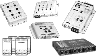
Another popular alternative is the Active Electronic Crossover in which the crossover action takes place in a unit positioned before the amplifier in the circuit. This requires the use of two or more amplifiers, each connected to the particular drivers ( midranges and or tweeters ) whose frequencies are delivered by the electronic crossover. This is a much more expensive, but very efficient, way to achieve the desired result. Individual speakers that have separate inputs for the various drivers are said to be Biamplified .
The term 'Crossover' indicates that point on the normal frequency spectrum between 20 to 20 thousand Hertz, (or cycles per second) where certain frequencies are muted, or rolled off to one driver and permitted passage to another. Thus, in a typical 3-way crossover, frequencies from 5, up to 1800 Hertz (HZ.) or so, are filtered and diverted to the woofer. Frequencies above that are sent to the Midrange up to 3500 Hz or so, and muted above that. Frequencies above the midrange band are filtered out and the remaining high frequencies are passed to the tweeter.
A mechanical crossover is typically a small dome or cone affixed to the center of a woofer that extends it's high frequency response, so that it becomes a so-called full range speaker. Electronic crossovers connected to independent tweeter and midrange drivers usually are much more effective in isolating the frequency bands within a spectrum, and at the same time, reduces intermodulation and other forms of distortion.

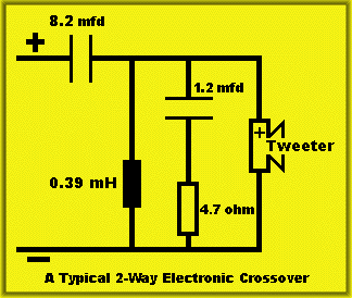
Above
is a schematic of a typical 2-way passive electronic crossover. Such
crossovers can be 2, 3, 4-way or more. They are circuits that for the
most part, use passive components such as coils (MH), capacitors(MFD),
and resistors(Ohm).
The woofer is connected directly to the amplifier and all the crossover
action is applied to the tweeter, in our example.
Be aware, however, that while this may work fine for certain types of
2-way speakers, the exact value, number, and configuration of the electronic
components are contingent upon the particular drivers used and the cabinet
characteristics of the speaker as a whole.
No crossover (passive or electronic) should be seen as providing rigid frequency dividing lines. In a simple two way design (one woofer and one tweeter) the designer might set a crossover point of 1800 hertz (also written as 1.8Khz or 1800 cycles per second (cps). This does not mean that all of the energy above 1800 Hz are sharply routed to the tweeter while only frequencies below, go to the woofer. There is actually a gradient, or slope up or down from the attenuation point. In fact, in some low budget designs, there is no upper frequency roll-off limitation for the woofer, beyond it's own natural response roll-off.. This means that for at least one octave of sound above and below the 1.8 kHz example frequency, (1 kHz to 4 kHz) the sound from the two drivers will intermingle and may cause interference. This can be either constructive or destructive interference; the knowledgeable designer takes this into account by utilizing not just the response curves of each driver, but their roll-off characteristics as well.
If the woofer and tweeter both have a peak of 3 dB at the same frequency, they could combine at this one point in the frequency band to make the sound "harsh". Conversely, if the speakers canceled each other,(i.e. one peaked while the other dipped, thus nullifying that particular frequency ) some of the important midrange frequencies would be lost, making the sound a lot quieter, thinner and less present. Thus, it is important to understand the characteristics of any replacement parts and how well they will integrate with your existing system, before they are put into your speaker.
However, and this is important , while this information could be very useful in helping you optimize your system, it is also very difficult to come by. Most car audio manufacturers do not provide the kind of detailed technical analysis, that makes it possible for the average audiophile to achieve optimal results. Thus, most of us make do with replacing defective units with drivers that are most similar to the original parts. Even though this method is obviously not as precise, the overall results are usually quite acceptable. This is one reason why most drivers should be replaced in pairs, (or four's, with surround systems) thus avoiding obvious imbalances on the sound stage.
MAIN
PAGE
GLOSSARY
SPEAKERS:
Choosing
General
Woofers
Miidrange
Tweeters
Full-Range
Full-Range 2
CAPACITORS
CROSSOVERS
EQUALIZERS
Theile/Small
AMPLIFIERS:
About
Installing
Install Tips
Power Ratings
RECEIVERS:
Installing
NEON/LED:
Installing
TOOLS
Home
--
Policies
--
Products
--
Tech
Center
--
Auto
Electronics
--
Home
Electronics
--
Personal
& Marine Electronics
--
Stereo
Tech Info
Website Designed & Maintained by
MetroDirect
Communications
Copyright (c) 2000 - 2009
Electronixwarehouse.com
.
Use of any material appearing on this site without specific written
permission is prohibitied by law.
electronixwarehouse.com
---
logobannerfactory.com
---
bleepthem.com (Political Satire)
---
rlebeaux.com
---
stereotechnicalinformation.com (Stereo
Technical Help)
---
electronixwarehouse.net
---
thespeakerstore.com
---
wmpublishing.com (Help For Writers)
---
barbarathenovel.com
---
cutethenovel.com


